Resurrection of an Opera 6
I received an Opera 6 which has been standing upright in a corner of a fellow´s music studio for years now. Being in the condition that it was when I got it, most people probably would have called it a scrap heap, I however called it a challenge.
Here I am trying to add to the various resources on the web so that others dealing with broken Opera 6es can find yet more helpful information.
The device initially showed the following faults:
- Broken fuse holder
- Burnt load resistor and worn out capacitors on the PSU board
- Advanced battery leakage
- …which of course introduced more errors
- Non working LFO III speed indicator LED
As a general advice, before going into detail I strongly suggest to keep yourself grounded (by a wrist band for example) when working on the circuit boards. Especially the voice board contains a bunch of hard or nearly impossible to replace ICs.
Disclaimer
If you use the information presented here you are doing this at your own risk. I cannot be held responsible for any damage done to your device or yourself caused by your actions! You need the appropriate skills to do work on electrical devices.
PSU restoration
To be able to work on the device at all I had to get the main fuse in again while the order of a new fuse holder was pending. Fortunately I had a flexible fuse holder at hand that I could solder in place.
I then had to replace the load resistor as well as two leaking electrolytic capacitors. Actually replacing all electrolytics is advisable in that case.
As suggested on this resource, I installed a trim pot in series with R6 to improve PSU voltage adjustment. Use a low resistance value as to not limit current flow too much.
I disconnected the PSU board from the other boards and made a rough adjustment of the required voltages. With the major damage on the CPU board due to the leaked battery a loaded adjustment of the PSU would not have made sense at that stage.
CPU board restoration
First attempt
I took out all the parts in the area that was visibly affected by the battery leakage and cleaned the area. I tested the resistors and they all measured good. So I put it all back together. I also added sockets to all ICs rather than soldering them back in directly. Then, so was my idea, I can start narrowing down pending problems and fix them one by one.
The first test run was very promising, it produced sound again! I was even able to load the factory patches via SysEx. Unfortunately, after a while all started to fail again. And from there on I´ve encountered each and every symptom that are described in the various chapters of sounddoctorin´s tech assistance page!
I started sourcing all the parts that I could get, and that even included the original RAM chips that I was able to find at a local electronics shop! I tried to narrow it down to specific issues, but apparently there where so many that it was nearly impossible to find out which is which and which had to be solved first as to rule it out as a primary or side effect for another one. So I put the whole thing aside for a while to give it another go eventually. When I picked up on it again I sought advice on a local forum to get new ideas. And the best idea that emerged from this was: Take another full attempt! Which led to the…
Second attempt
Cleaning the board again
It became quite obvious that there where still major issues with the board caused by the battery acid. So I decided to completely disassemble the affected area again and give it another good clean (At this point I can only suggest to get a desoldering station to make your life easier here!).
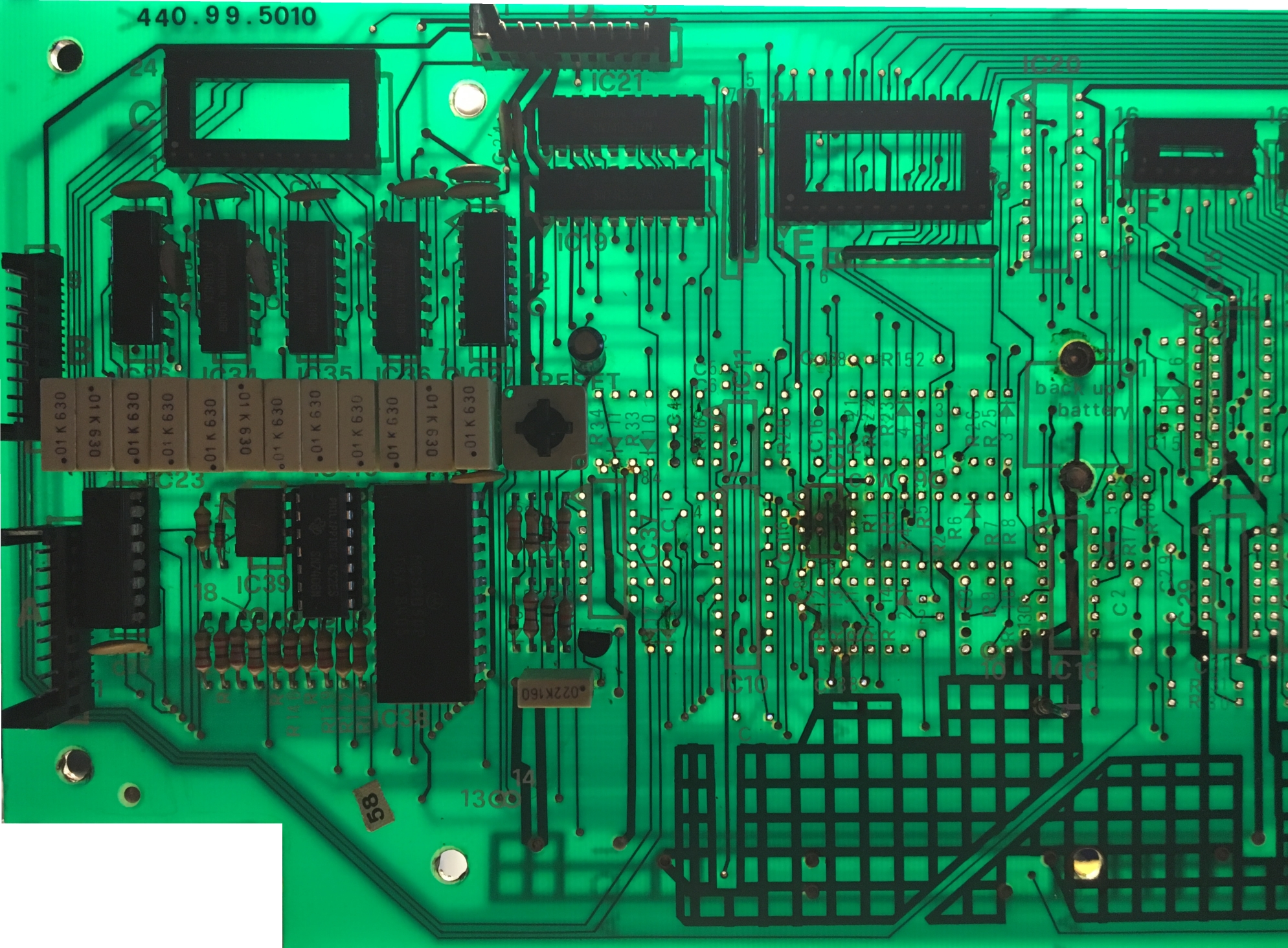
Opera 6 CPU Board top view – cleaned
Sourcing replacement parts
I decided to replace all the parts that I removed from the affetced area, no matter what. So I put all the parts into a box and then seeked and ordered replacements for them one by one. For your convenience, here is a list of the replacements that I used:
| Part | Original Type | Replacement Type | Comment |
|---|---|---|---|
| Transistors NPN | BC 239 | BC 549B | TO-92, 30V, 100mA |
| IC11 | TL082 | TL082 DIP8 | Any |
| IC12 | LM393 | LM393 DIP8 | ST Microelectronics |
| IC13 / IC14 / IC22 | 74C174 | M74HC174 | ST Microelectronics |
| IC15 | 74LS244 | SN74LS244 | Texas Instruments |
| IC16 / IC37 | 40106 | HCF40106B | ST Microelectronics |
| IC20 | 74LS377 | SN74LS377 | Texas Instruments |
| IC28 | 4001 | HCF4001B | ST Microelectronics |
| IC29 | 4011 | HCF4011B | ST Microelectronics |
| C1 / C2 / C16 | 100nF | MKS-4-250 100N | WIMA |
| C3 | 1nF | MKP-10-1600 1,0N | WIMA |
As per service manual page 6, all diodes are 1N4148 and all resistors are 1/4W.
Reassembly
This was the really time consuming part! Here I wanted to make sure that all traces are conductive and everything is up and running again.
I´ve used the following tools:
- Soldering station
- Multimeter (DMM)
- Braided wire
- A copy of the service manual
Now I had to decide how to proceed. One can reassemble the parts from left to right, by functional unit or by part type. It is advisable to put sockets for all ICs in first, because most other parts connect to them. This way one can assure the connectivity along with the respective part. Fortunately, every part number is printed onto the PCB.
So here´s what I did
- Set DMM to continuity test mode
- Seeked out a part to put in and located it in the schematics
- Soldered the part in place
- Took the DMM and checked conductivity of each solder pad, trace and via that the part connects to according to the schematics
- If a connection was not conductive, I applied a point to point connection with braided wire
- Did this for all parts (<-This is what makes this a lengthy process!)
Finally, put in all ICs and put the board back to where it belonged.
Time for a test run… Worked! Not all of it, but the core was back up. All voices played and the device loaded the presets via MIDI and held and played them. Also, most of the controls worked like they should.
Here is a picture of the reassembled board
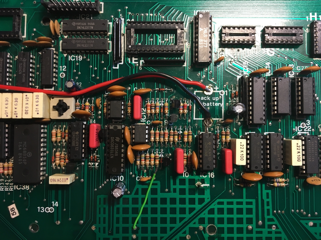
Opera 6 CPU board (top) serviced
Remaining faults
Apparently, no matter how thoroughly you are trying to work, the chances of overlooking something are there. But, other than after the first restoration attempt, the remaining errors where clearly definable and locatable. So one after the other could now be addressed.
Inoperable Push Buttons
Some of the push buttons on the panel did not work. The first step was to find out what seperated the working ones from the non-working ones to narrow down the origin of the fault. Since all buttons on the panel are processed by a single matrix decoder chip, I set up a matrix on a spred sheet and marked those cells that did not work. This revealed that the error spread across almost all lines of the decoder matrix, so the decoder chip itself could not be the problem. Also its address lines and DAV (data available) output showed just fine on the scope. Another look at the schematics showed that all non-working buttons where handled by the Flip-Flop IC20. All signals arrived ok, but there was no change at the respective outputs. I eventually found that the enable line EN2 between IC8 and IC20 was not working. A point to pint wire fixed the problem and the buttons where all functional except one.
LFOIII to PWM A enable
Despite the above fix of the push button circuit, the PWM DCO-A switch still wasn´t working, although PWM DCO-B did. The both of them share a button, so the circuitry between the panel board and IC20 could be ruled out, which was prooven by the output of the respective FlipFlop (IC20/9) measuring just fine. This output goes to IC52/10 in the generation section of the CPU board and there I found nothing. The culprit was an invisible crack between the solderpad of IC20/9 and the trace.
LFOIII Rate LED
The Rate LED is fed from IC49 on the CPU board via IC6 on the control board. A comparator signal at TTL level triggers a buffered inverter which drives the LED. In between are two connectors. As the signal has to travel half way across the CPU board and given the origin of the previously fixed errors, the source of the problem may well be another faulty track.
And so it was, but not on the CPU board. When signal to the LED measured okay, I desoldered the original LED to replace it. And not was the original LED burnt through, but also the ground solder pad came off upon desoldering.
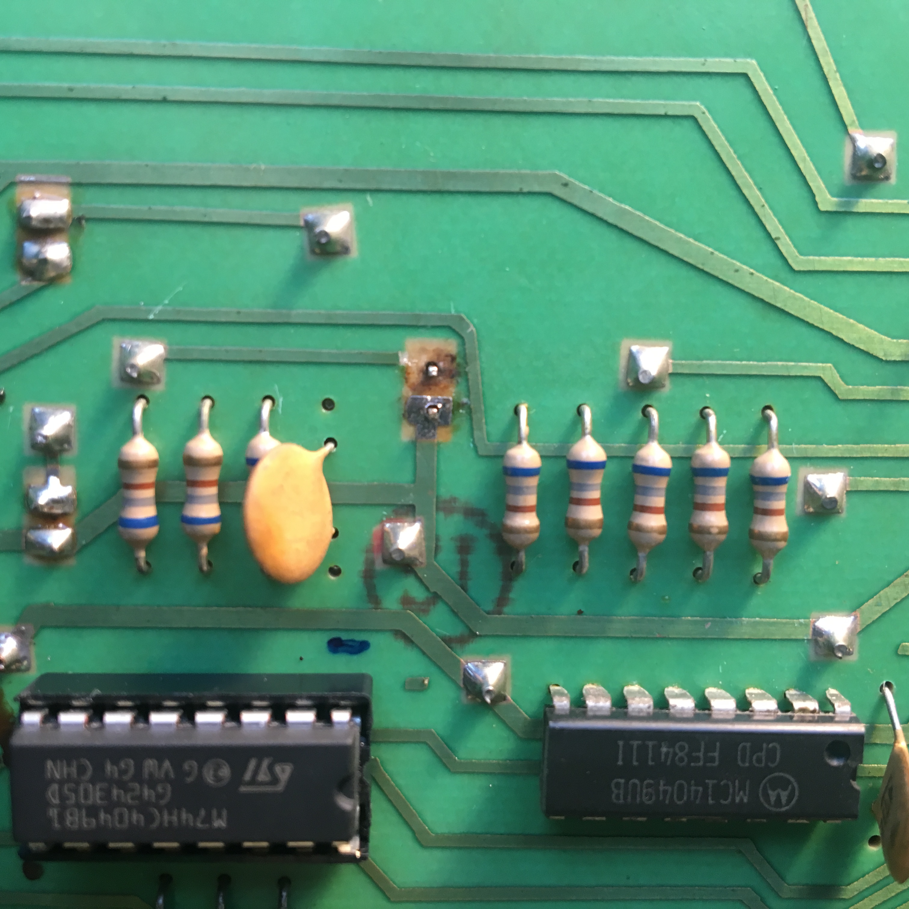
Opera 6 – cracked LFO3 LED solder joint
I then just used the ground leg of the replacement LED as a bridge to fill the gap.
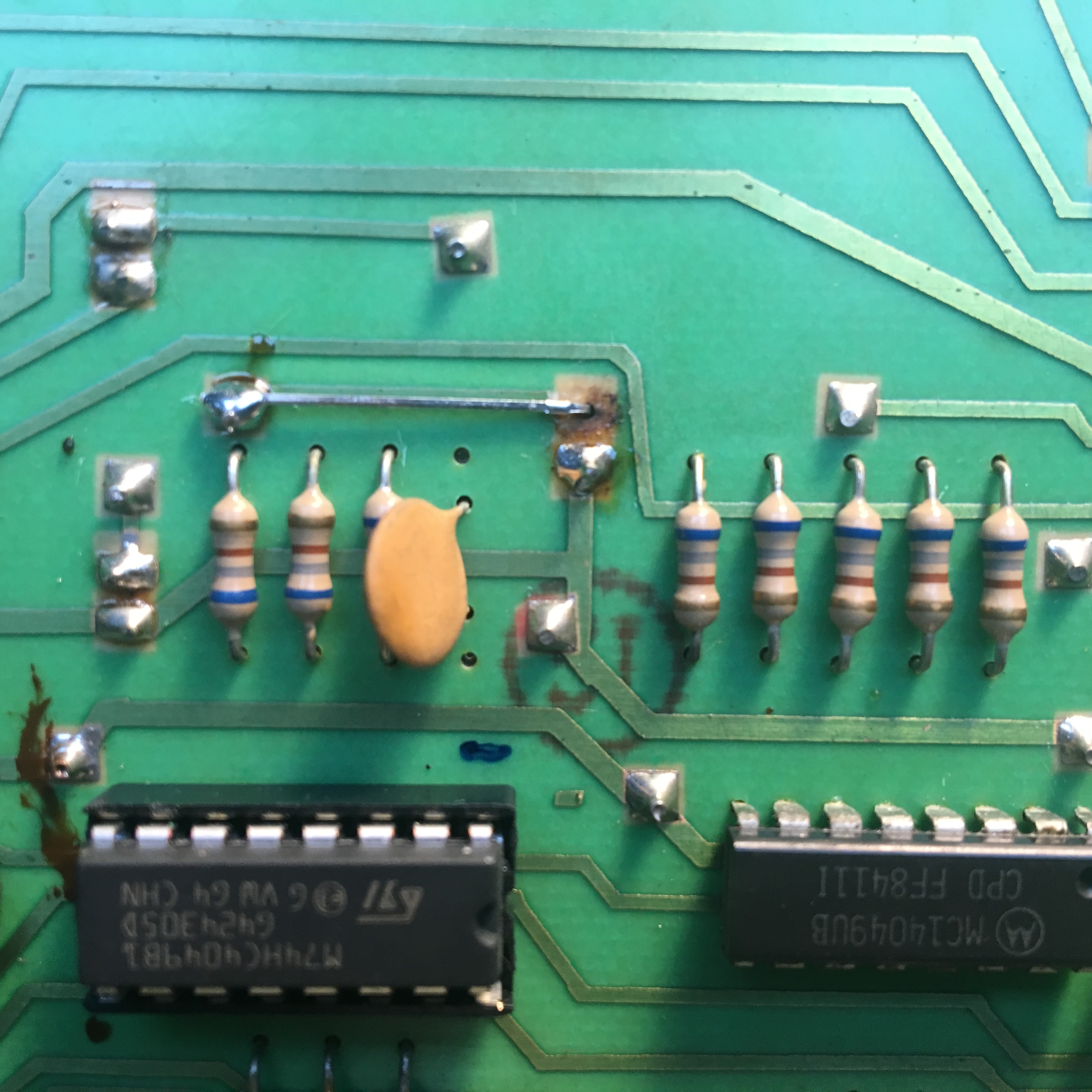
Opera 6 – fixed LFO3 LED