This is a follow-up to the general modification article.
In an effort to come up with a more detailed documentation for the mod I made an annotated picture of the mainboard followed by some explanations:
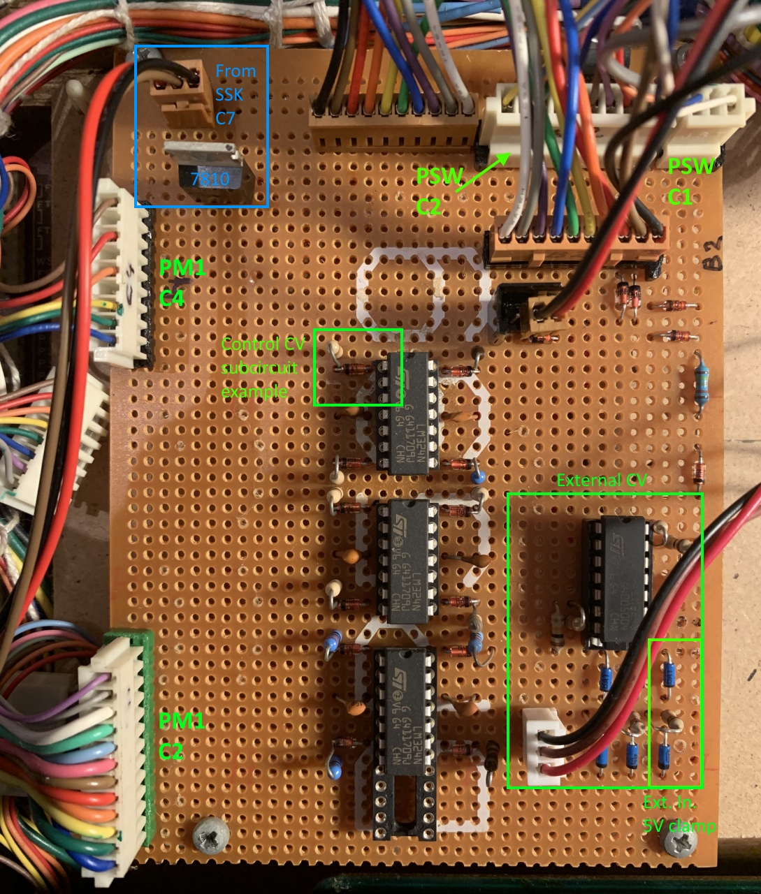
Yamaha CS15D DXmod mainboard annotated
Explanations of annotations
Power supply
In the upper left corner, in blue, you see the power supply subcircuit for the board (see also The Tr7 Problem in this article).
The connector goes to connector C7 on the SSK board, which is fed with +/-15V directly from the PSU board. The various OpAmps on the board connect directly to it. Also the +15V line feeds the μA 7810 voltage regulator, which feeds all the potentiometers.
Control CV subcircuits
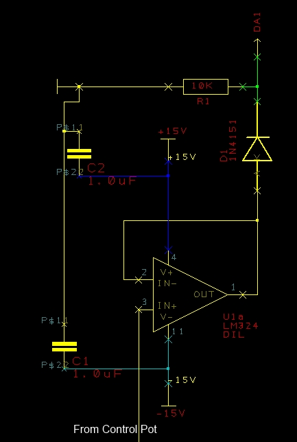
CS15D manual control subcircuit
The control CV subcircuits are built around the three LM324 OpAmps in the board center.
The inputs (From Control Pot) are connected to the two brown on-board connectors which connect to the potentiometers and switches on the control board.
The outputs go to the two original connectors PM1-C2 and PM1-C4.
PM1 C2/C4
These two connectors are the original connectors that are normally connected to the PM1 preset board.
PSW C1/C2
When installing the modification, not only is the preset board for channel one removed, but also the presets for channel two.
Therefor we need to implement the functionality of the channel 2 Manual switch. This is done by simply shortening pins 1 (+10) and 3 (MS2) of connector PSW-C1.
PSW-C2 is connected because we need to feed the 10V CV voltage to the control section of channel two. This is done via pin 9 (MS1) of PSW-C2.
External CV
I have installed three external control volatge inputs for pulse width, filter cutoff and resonance amount. They are simply added the respective control pot inputs of the OpAmps.
The external inputs are laied out for input signals in the 0-5V range. To assure the input rating each input is equipped with a clamping circuit which I took from Doepfer´s DIY page.
Since the CS15 works with CVs of +10V internally, the voltages are amplified by 2:1 non-inverting amplifier circuits around the LM324 on the lower right of the board.
Wrap-up
That is basically the whole shebang of the mod. I will try to come up with proper schematics of the board eventually. I have already started it.
But actually, if you are to eager to do the mod yourself and don´t want to wait, you should have sufficient information now to go ahead. You would of course have to find the correct values for the control pots in ther sevice maual, but if I could do it you can do it.
For discussions please refer to the muffwiggler thread.
So long…