Tag Archives: modifications

Midiverb II repair

I´ve had a broken Alesis Midiverb II lying around for quite some time now. Just recently I remembered that I´ve always liked Patch #28, even before I dove into ambient and drone. So I thought now was finally the time to open it up and give it a go, especially since not to long ago I aquired a Midiverb 4 from an old friend and thus had a working 9V AC/AC adaptor again which the Midiverb II also requires.

Symptoms

You´d plug in the power adaptor and nothing would happen, neither visually nor sonically. The unit was basically dead, or so it seemed …

Fault trackdown

It´s always a good start to make sure that all the supply voltages are there and within range. The Midiverbs rectify internally so I started at the power adaptor plug and made my way through the PSU unit. Power on all paths was present but at very low ratings. I unplugged it again and did some continuity measurements. I found a short circuit between the output and ground of the 7805 regulator. I took it out and found that it measured okay out of circuit so it itself couldn´t be the problem. I still had to replace it because the input leg simply broke with no real force applied,

The repair

So there was a short circuit on the 5V supply line. I measured continuity across all capacitors and marked al those that seemed short which I then soldered out. Basically I removed all ripple filter caps of the digital ICs. Subsequently I no longer measured a short circuit across the 7805. It turned out that two of the filter caps had shortened. I replaced those with 470pF that I had left over from the Opra 6 repair and put all the other working ones back in.
That was all it needed. Plugged in the adaptor and there it was up and running again.

Improvement

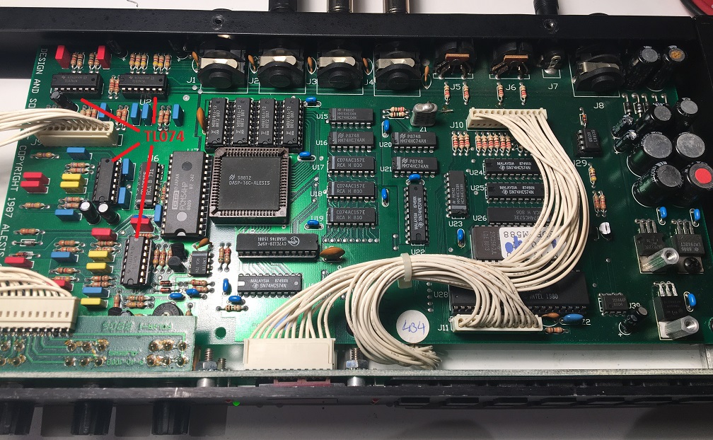
I noticed that the unit emitted a slight humn and a significant amount of noise when cranked up fully. I then remebered that the device has always been a little noisy. I realized that it might be a good idea to check whether the analog circuit could be improved upon. All opamps where LF347 and a little research revealed that the TL074 is compatibel and seemed to have better ratings. So I decided to replace all LF347 with TL074. I used sockets just in case that I where proven wrong and had to reverse it, which didn´t happen. I am quite stisfied with the improvement and really happy to have the unit back in working condition.

Midiverb 2 TL074
Midiverb II w. TL074

CS15D channel 1 modification

Since I got my CS15D I´ve always known that one day I would make a certain modification to it, and this day has finally come: Manual control for channel 1.

Mod design

When I opened the synth the first time I was pretty surprised by what preset meant before the time of (affordable) digital memory! Each preset is a set of resistors defining the CV values of the parameters.
The channel 1 and 2 presets reside on distinct PCBs.
I eventually managed to grab a copy of the service manual, and it made it pretty obvious that it would not be too hard to replace the presets by controls. The service manual reveals that all parameter CVs use the same 10V voltage source. The preset selectors route this source to the respective preset subcircuit. Channel 1 manual mode is not so much different. The voltage source feeds the control pots that are buffered by op-amps.

CS15D manual control subcircuit

CS15D manual control subcircuit

The overal design of the synth proved execellent for the modification.
The preset selector switchboard can be easily unscrewed from the front panel and the panel slits provide enough space for the new pots.

CS15D preset switch panel

CS15D preset switch panel

The preset board for channel 1 can also just be unplugged and taken out, and the board connectors reused to feed and source the modification board.

CS15D channel 1 preset board

CS15D channel 1 preset board (PM1)

This design makes it easy to replace the original components with the custom control modification without altering the original circuits or messing up the front panel.

Now the modification was pretty straight forward:

  • Build a PCB with the driver op-amps, voltage source routing and board connectors.
  • Build a control panel

It was not so complicated, but a lot of soldering work..

Once finished, I hooked it all up, switched on the synth and… It worked!
But just for a short time, which brings me to….

The Tr7 problem

A minute after I started calibration works on channel one, a flashy bang to my left silenced the audio output of the CS15. After a short notion of anger and a little fear I might have damaged an irreplaceable custom chip, I searched for the fault and located it soon: A transistor blew into pieces. Lucky enough the marking on the front was still readable, and a glance at the service manual revealed the function of the destroyed part. Tr7 on the VCO board is the actual 10V source for the preset circuit, regulating +15V from the main power supply down to 10V.

I first assumed I caused a short circuit while calibrating which lead to the destruction of the transistor, so I simply replaced it with a new one and went from there. Not long though till the replacement gave up, too. So obviously my modification lead to an overload. I replaced the voltage source for my mod board with a power supply generator, which told me my circuit draws ~30mA. The transistor provides a base-emitter current of 150mA, so my assumption didn´t seem so far fetched.

I then decided to include an 7810 voltage regulator into my board, feeding it directly from the main power supply. And what can I tell you… problem solved!

Summing up

Yamahas design for the manual controls has a very handy side effect. The driver op amps can also work as CV mixers. So you can easily hook up an external CV input in parallel to the control pot for each parameter. Due to space limitations, I did that for pulse width, filter cutoff and resonance. Now I can feed in an LFO from my modular, too. But this also leaves some space for improvement on my circuit. The eurorack modul CV voltage is in the 5V range. The CS15D works with a 10V range. So I still have to include amplification for the incoming signals…

The happy ending

The mod works and I am very happy with it. I am not so much a fan of presets anyways and it never made sense to me to create the sound of a trumpet or clarinet with an analog synth. So now I have a brilliantly sounding synth with two manually controllable channels.

For the below video I hooked up MFBs Urzwerg to each of the channels CV/Gate inputs (via a CV converter of course) with two slightly different sequences. One channel plays the bass part and the other one the melodic part. In addition to the sequence I recorded two solo melodies.
Yamaha CS15D modified from MacroDX on Vimeo.