I have been wanting to add individual outputs to the TR-505 for quite some time and after I installed the HKA Rom Expansion I did so. I found this page and followed the instructions on it to build in the individual outs. After some testing I soon found out that the mod did not fully meet my expectations. The culprit of the remaining original mods is that for the most important sounds, the volume envelope is bypassed, thereby introducing digital grit into the sound decay.
About 505 sound channels
The 505 creates the sounds by demultiplexing the sound data from the sound ROM onto mutliple audio lines, already combining some similar sounds, like all tom sounds. So far so good. Unfortunately for the modder, other individual sounds like bassdrum and snare are mixed together into one buffer amp right after the decay envelope generator. As statet above already, this volume decay prevents digital noise to overshadow the actual decaying sound.
The monophonic output of each buffer amp is then split into two signals to feed the left and right output channels.
Applying individual outs
… by going in full. Well, I do not mean to diss the solution from the better mod page, after all it is the best mod you can achieve without additional components. I do however think that when you already make the effort, you might as well do it properly. This applies to the the sounds that are mixed together into IC16/b, which are bassdrum, snare, handclap/rim, the cowbells and the congas. Given that these are 5 different sound lines, you only need one additional 4 channel op amp, as 16/b can still be used for one of the sounds. Basically each of these op amp channels needs to copy the circuit of 16/b. But this still leaves one problem to solve:
How do these sounds get decoupled from the main mix and also get mixed when not plugged out as individual outs?
This can be solved by using a stereo TRS socket with switches. But there is yet one thing to consider: When a mono plug is inserted, the ring connector of the stereo socket will be connected to ground. Therefore it is best advised to connect the buffer output to the ring switch instead of the ring tip, thereby instead of shortening the buffer output to ground, tying the mixing resitors to ground.
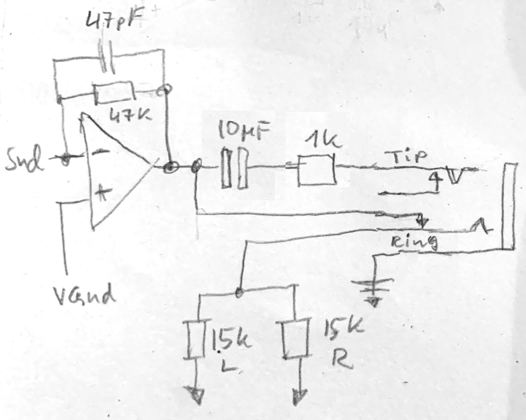
TR-505 individual output sub circuit
I´ve added a 10uF bipolar coupling capacitor, which is omitted by other mods. It may not be that big of a problem when using external mixers, which probably have a coupling capacitor somewhere in the signal path. But you may want to consider that the biffered signal paths are offset by the virtual ground DC level of about 2,5V.
The hardware stuff
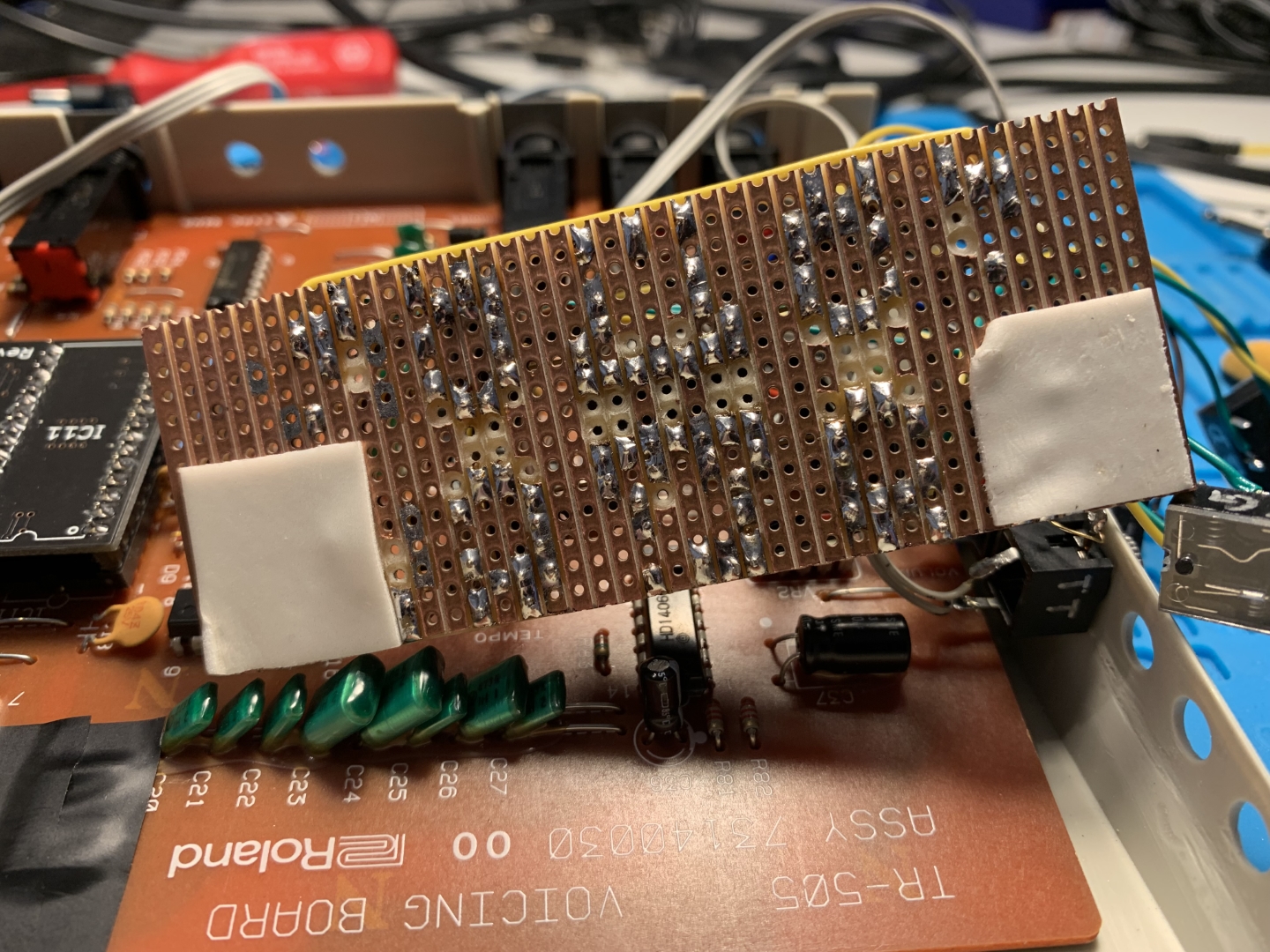
Auxilliary PCB
We need the above illustrated subcircuit times four. I simply put this on a stripe board because it seemed as the easiest option.

TR-505 Individual Output PCB
Note that for the op amp, though the picture shows a TL074, I went with a TL064 in the end because of three reasons:
- There is enough headroom so that the amplification does not reach the limits of the 64 causing distortion.
- The 505 samples are 8bit, 25kHz only, so high fidelity does not apply anyways
- The TL064 only has 1/10th of the current consumption of a TL074, therefore being more suited for battery operation
I compared both types in the arrangement and did not hear any difference.
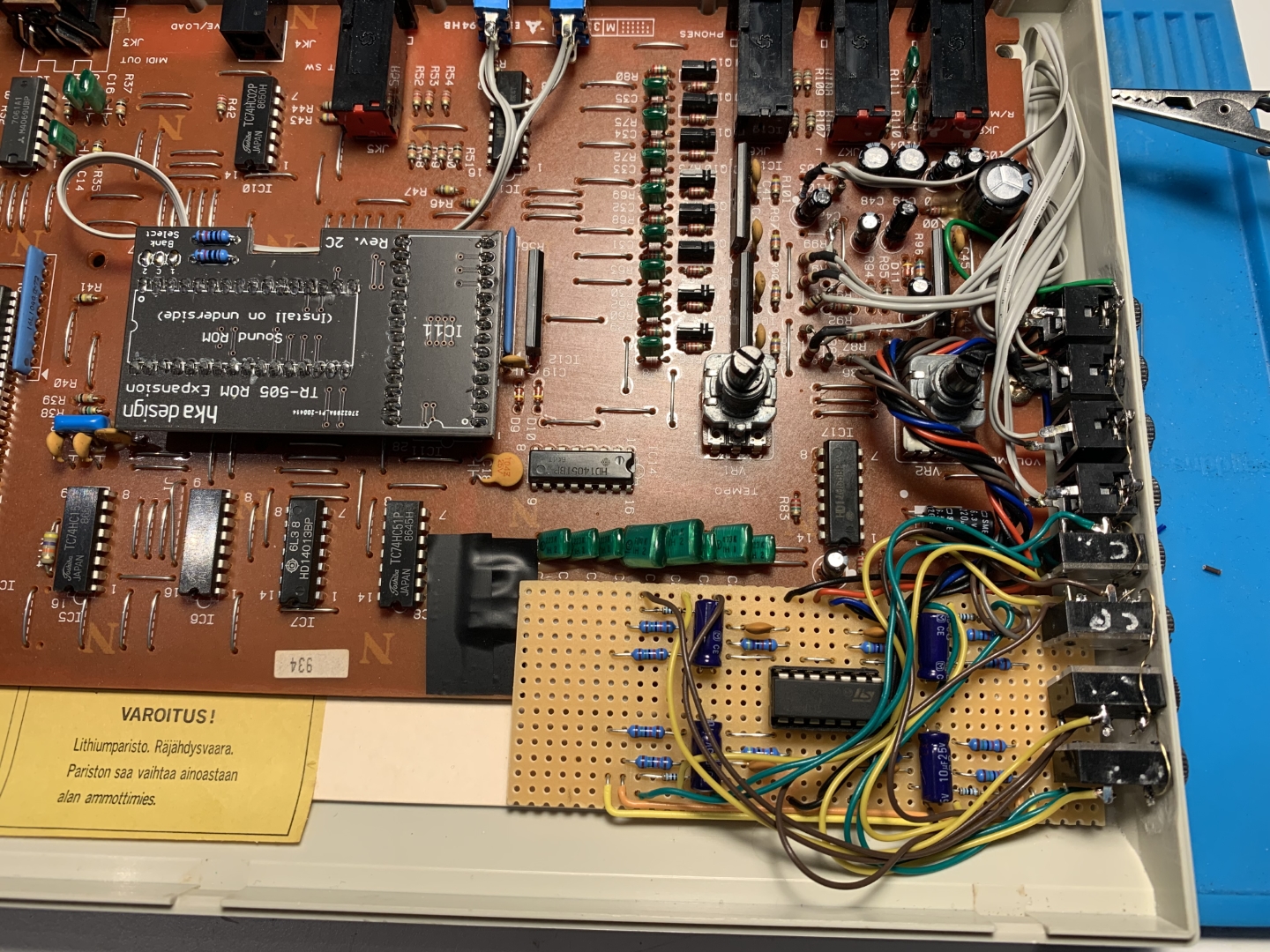
To hook up the auxilliary PCB to the mainboard, some traces on the mainboard will have to be cut to break up the connection to the mixing buffer (see the yellow frames in the below picture).
the inverted input of each individual buffer amp is hooked upt to the emitter of the respective sound channel´s decay envelope transistor (see the red circles in the below picture).

Hardware penetration
Yes, it cannot go without, because we want to cramp a lot of additional stuff into the housing.
We need a total of eight holes for the sockets.
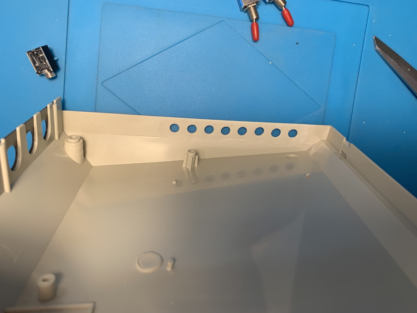
Unfortunately, to fit the stereo sockets, I had to cut away some of the switch panel PCB. But fortunately enough, all the space was ground plane, so it didn´t really hurt.


I simply fitted the auxilliary PCB using double sided adhesive tape.
With everything fitted, the insides of the 505 now look like this:
Conclusion
Considering the hours I had to spend on figuring out a prototype, soldering the PCB together, working on the housing and putting it all together I would say: If you are the DIY type who considers the path to be the goal, go for it. It´s a little challenging but also fun. If you only want a 505-like drummy with individual outs, take any sampler loaded with 505 samples or save up your money for a TR-707 ;).
Oh, and here´s a little disclaimer: Should you follow any of my proceedings above to modify your 505, I cannot be held responsible for any damage you cause on your device ¯\_(ツ)_/¯